Software waveform displays and vectorscopes in the software of your choice might not always show you what you need to know. Especially when you need to adhere to broadcast standards, this can be an issue. This little post outlines the problem, provides some examples and on a quick fix.
Scope vs. Scope
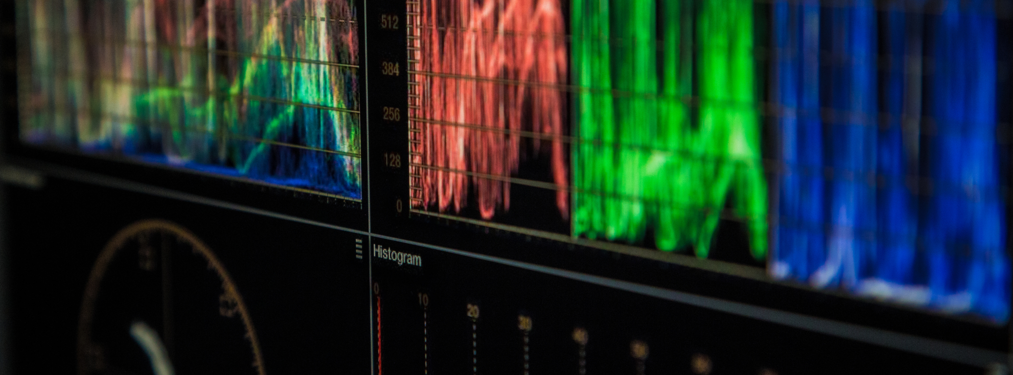
I’m monitoring what I get from an AJA KONA 4 via dual SDI as YUV-10 on a Tektronix WFM 8200 scope, which lets me see the “actual signal,” so to speak. The scopes in the software of your choice instead show you an interpretation of an image’s pixels of how they would look like as a video signal.
To my understanding, the difference is that certain factors are influencing the signal that goes beyond mere pixel values, e.g. how pixels with different intensities are located spatially. That’s a very fancy way of saying that when pixels with very different intensities are next to each other (i.e. hard edges), it affects the waveform of the actual signal. I haven’t encountered a terrible software-scope yet, then again I’m a fastidious long-time WFM 5200 and recent WFM 8200 user.
Software scopes need to cut some corners because plotting a waveform from millions of pixels many times per second is rather taxing on the processor(s) already kind of busy performing the color transformations of your grade. Scopes need to simplify things a little; they might not update on each frame during playback, only plot every other pixel (or even less), or even use approximations.
And that’s okay, since real-time playback has a higher priority than accurate scopes in your application, especially with clients around. In a proper color grading suite you’ll have external scopes anyway so that’s not a real issue. But it can be a problem when you’re an indie producer who shoots, edits and colors on not much more than a MacBook and a tight deadline.
Broadcast
In this little article, I want to look at the Number One reason why something that perfectly looks valid on your in-software scopes doesn’t make it through quality control for broadcast. Despite many stations today broadcasting their content digitally, there is still the need to adhere to the specifications that were once put in place for terrestrial broadcast. That’s the murky realm of electronics terms such as colorburst, phase-alternating line, and quadrature amplitude modulated sub-carrier which I won’t get into.
Most important in our context is the maximum allowed brightness of a video signal which corresponds to the voltage of the signal. The problem is this that the output signal can over- (and under)-shoot the legal range in certain circumstances. Some spikes are okay, but having the signal too strong for too long is bad. I’ve heard stories from the ancient days of analog broadcasting where such an issue caused a transmitter to burn out; the voltage of the broadcast signal was too high for too long. Again, today that’s not as lethal to a TV station as back in the day but then again who knows where your delivery might end up one day.
Overshooting
These unwanted spikes that cause the signal to overshoot are caused by high contrast situations, when a pixel with a very low voltage (= brightness) is right next to one sporting a high value that causes the signal to keep oscillating after the voltage spike, i.e. to overshoot.
Let’s look at some pictures. Here’s a simple checkerboard:
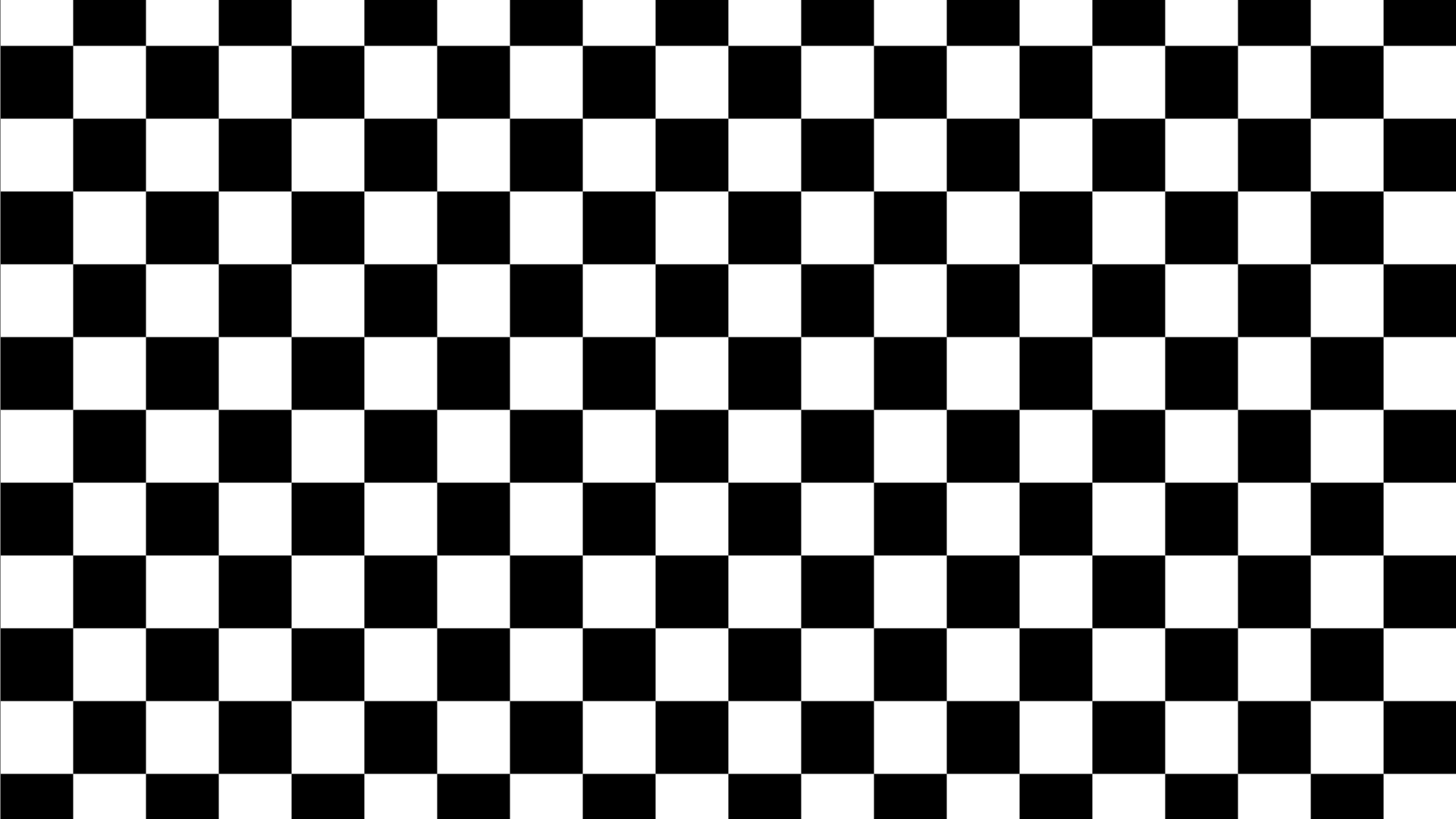
Instead of the tiles simply being 100% black or 100% white, the checkerboard generator in After Effects applies some simple filtering, lessening the contrast between the pixels with pixels of 50% intensity, as is plain in this close-up:

While this reduces the threat of overshooting, it’s still not enough, as we sill see in a minute In Resolve I put the checkerboard in a sequence and took a screenshot of the waveform readout.
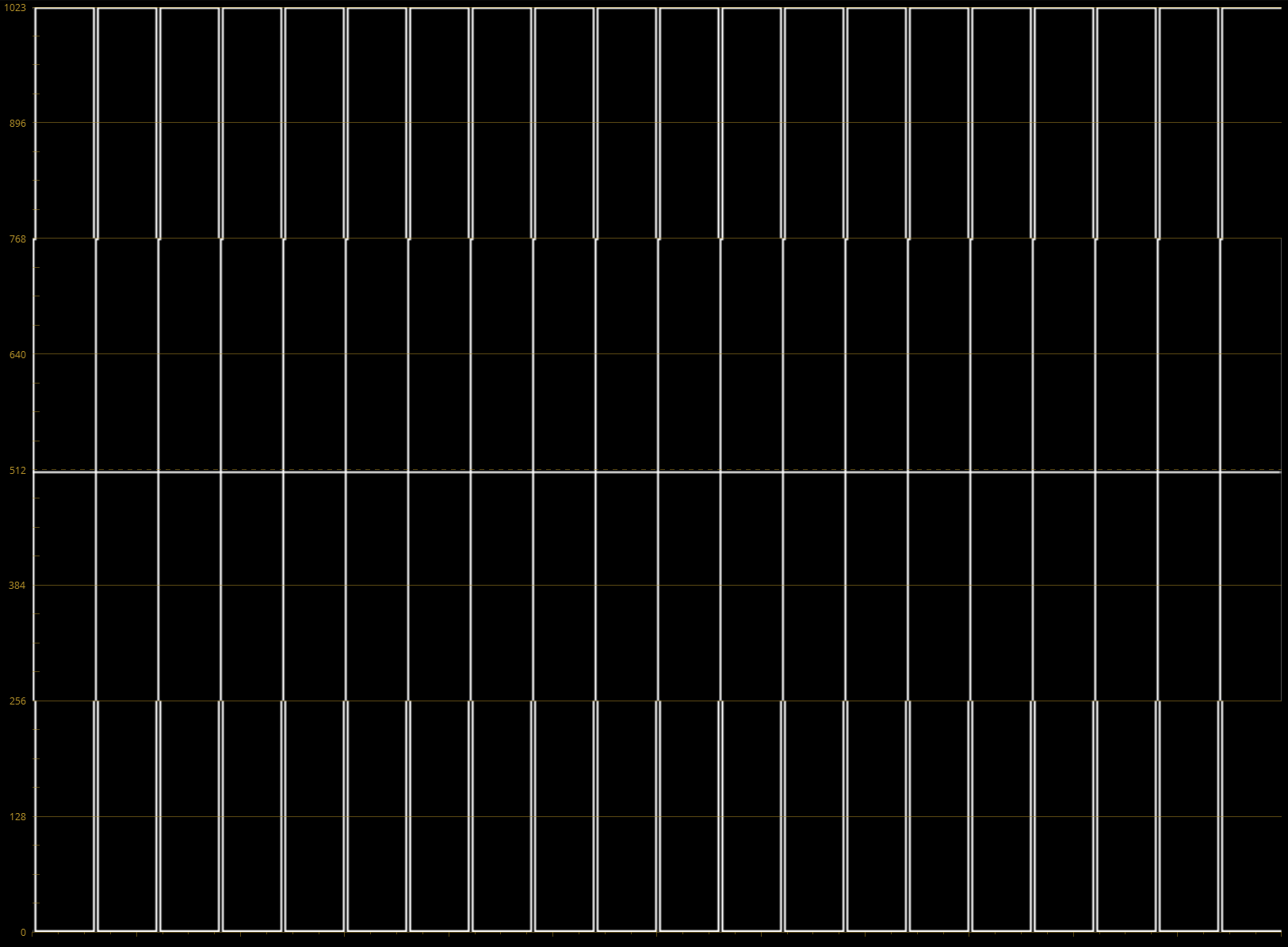
At first glance, everything looks fine here, no apparent post-pulse oscillation. The only odd thing to me is the tapering of the lines around the 256 (= 25%) and 768 (=75%) values. I attribute this to sub-sampling on Resolve’s part, apparently the original image has some filtering applied prior the waveform gets plotted.
How this is what it looks like on the WFM 8200:
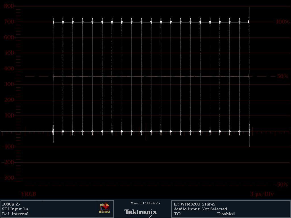
Quite a different picture. For one thing, the aliasing at the 25% and 75% values is gone. And there are visible spikes that go beyond 100% and below 0%. That’s not too terrible, and it will pass most clients’ quality control instances unless they are nitpickers by virtue.
Real-world(-ish) Example
Unless you are grading the Chess/Checkers World Championship on a regular basis, the checkerboard example from above is not often that applicable. Let us have a look at a different example that’s pretty much the norm in broadcast: Titles.
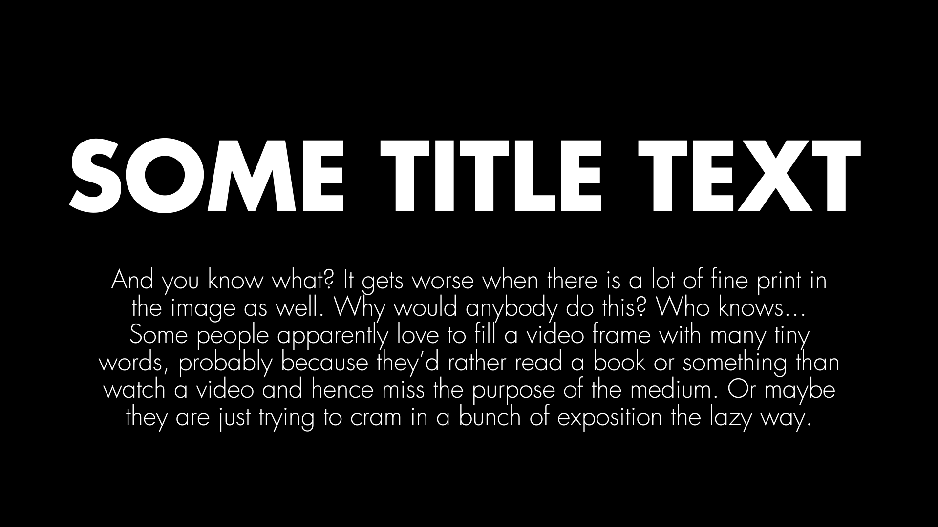
This little headline was created in After Effects with the default settings, just some pure 100% white Futura Bold on 0% black with standard anti-aliasing:
A look at it on Resolve’s waveform monitor:
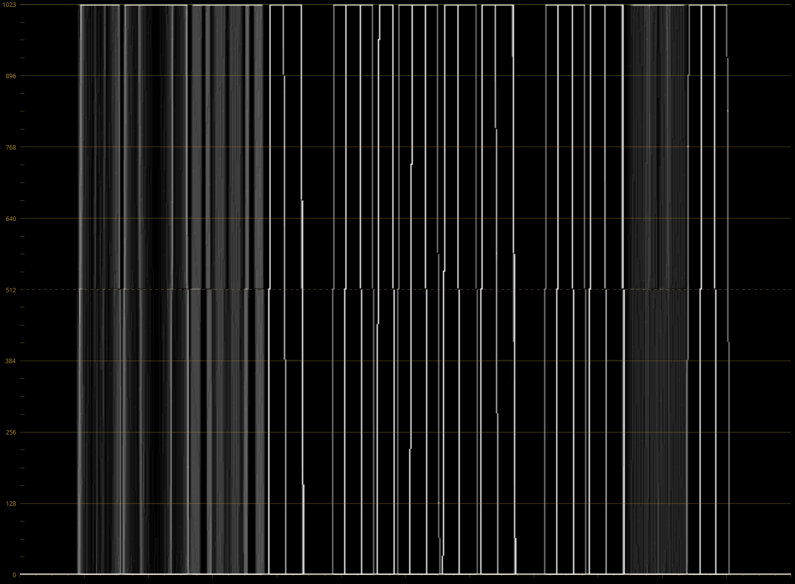
Thanks to anti-aliasing there’s a bit more going on, but everything looks peachy here. But on the hardware scope it’s a different story:
The signal is overshot by 100 mV in either direction; that’s ~15% more voltage on top than there should be. And guess what? This gets worse, the more of those contrasting pixels you have next to each other. How about some more text?
In Resolve, the scope gets busier but it can’t show you what’s really wrong.
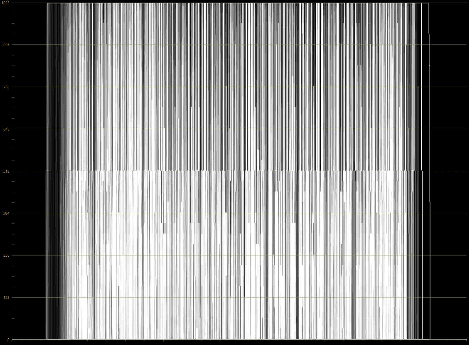
I don’t know about you, but whenever I see a waveform cut off like that, I get an uneasy feeling. Probably because of how this looks on the external scope:
Wow. Here we’re even beyond 800 mV, probably even off the chart. And that’s not good for sure.
Step 1: Awareness
As you see, this issue is impossible to track with the scopes inside your favorite grading software, so hopefully, I created a bit of awareness for it. The whole matter is not so much an issue if you’re producing for anything that doesn’t run the chance of ever being broadcast; then again we still carry a lot of baggage from the early days of television still around (at least BT.2020 finally dropped interlacing!).
Even if you have no hardware scope at hand, be mindful when working with graphics and titles that you create in Photoshop or After Effects or get from somebody else working with those tools. In my experience, when graphics departments give you something “broadcast ready”, it usually means that they merely slapped an out-of-the-box broadcast-safe effect on top everything before rendering. That’s not an issue in Premiere, though: The title generator has been slightly blurring text for ages now because thin typography would overly flicker when displayed in interlaced SD. Oh, old times… good riddance!
Also, when you have to work with recordings from consumer cameras that have an aggressive sharpen filter active this can occur in a variety of situations, e.g. on silhouettes of branches against the sky, gravel, crowd shots, and so on. A cold comfort here: Usually the compression profile can’t handle that much detail anyway, and the image gets blurry with artifacts.
Step 2: Fixing it
Don’t just lower the whites until the spikes are somewhat in the legal range again, because it makes it visually unappealing when in one shot; the whites are suddenly a bright gray. Instead, there’s a simpler fix that worked every time for me:
Just blur it.
Really. A Gaussian Blur with a radius of one pixel is enough and gets rid of that problem entirely. Occasionally I’ve had clients complain that it makes the resulting image not “pop” enough, that’s “it’s not HD enough”. I urge them to look at the result on their TV set at home because consumer TVs with all their fancy image “enhancements” sharpen the living crap out of anything anyway, blurry by one pixel is totally acceptable.
Here’s what this simple tweak does to the example above. Here’s again what it looked before:
And after:
Visually almost identical, signal-wise now perfectly legal.
I hope this little article was of help to any of you!